Templates
Templates allow you to define which set of parameters will be reported on for a machine. This includes; Values, Alarms, Locations and Actions.
To navigate to the Templates section, under Admin, select Templates.
This will display all available templates that you have created. To configure/edit any of the existing templates, click the Config button next the to template you wish to modify.

- A. Modify Button
- Allows modifying values such as the template name, description, datatag, etc. Click on the green check mark to save changes or the red X to cancel.
- B. Messaging(Alert Contact)
- If this check box is unchecked, the system will ignore the 'Alert Contact' check box of child parameters and users won't get email alerts.
- C. App Class
- The type of application the equipment is used for. Determines which mobile app the device is visible in (Currently: amslink, atmlink, and boatlink).
- D. Offline Timeout
- E. Expandable Menu
- Add new rows from here.
- F. Edit Icon
- Puts a row in edit mode.

- Click the green check mark to save or or red X buttons to cancel changes. The red trash icon on the far right deletes the row.

- G. Swap Parameter Position Icon
- Changes the display position of parameters on the equipment management page.
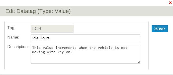
- H. Edit Datatag
- Datatags have names and descriptions that are used when the name and description is left empty on a row. Datatag names and descriptions are company wide. Changing them changes the name on all rows that don't have their own name and description and that use the datatag. Datatag names have been pre-populated with the most common names from the rows that were using those datatags.
- I. Description
- J. Add Resettable Meters
- See Resettable Meters
- K. Value Ranges
- See Value Range
- L. Delete
- M. Toggle View Button
- Switch the view to Tab view or Stacked view.

Contents
Values
In order to add a Value Parameter, click the New button from the expandable menu of the Values tab. This brings you to the Enter Value Params screen shown below.

There are a number of configurable options:
- A. Value #
- DPL devices internally identify types of values by their value num. The value definitions created here are used to configure the rest of the parameters such as names, descriptions etc, tied to these value nums. There cannot be any duplicate value nums in a set of configuration rows of a template.
- B. Tag
- A datatag. Only allows the uppercase alphabets, number, '_' or '%'.
- C. Name
- Leave empty to use the datatag name.
- D. Description
- Leave empty to use the datatag description.
- E. Optional Formula
- Pre-defined formulas to convert the raw data to a particular format.
- F. Extra Formula
- Extra mathematical formula. When there is an optional formula, the extra formula will be applied after executing the optional formula (Subject to the condition the optional formula output is numeric).
- G. Alert Contact
- Send e-mails when a value comes in to configured alert recipient (Configured in Accounts).
- H. IsCounter
- Calculates deltas. The delta will be zero for the first data point after a DPL device is associated with a piece of equipment in emms whether this is after a first installation or after a device migration to this equipment. This is done in order to ensure the records are unaffected by residual data from a previous device installation on another equipment and to inhibit large deltas from initial values of ECM provided values such as odometers.
- I. No Fix
- (Deprecated) Normally, when fixing data to a past reset point, the data is assumed to have been hardware reset to zero and need an upward correction to make it seem like it is continuing incrementing across the reset point. If set, there won't be an assumed reset to zero and data won't be corrected upwards. This is necessary for values that don't reset to zero for example when they come from engine ECM. Note that this feature will become useless as resetting and fixing data has been deprecated in favour of moving device serials across emms equipment.
- J. Correct Device Side Reset
- If this is set, value accumulation is managed server side. The value is continuously incremented (unless a manual data reset on eMMS) and is corrected for downward jumps caused be hardware resets or device swaps. This setting only applies to counters. Currently the first value received for a new equipment in eMMS becomes the initial value shown. Residual accumulated data from devices that were not reset properly before being reused may show up as the first value on a newly created equipment. If this is not set, raw values reported from hardware are shown. This can be useful for things like Odometer values from ECM or other counters completely managed by hardware (This setting was formerly called "Resets on Power Cycle").
- K. Ignore Zeros
- L. Admin Only
- Not visible to normal users.
- M. Location Special Data Type
Resettable Meters (a.k.a. Service Meters)
Resettable meters increment following a parent device value but are manually resettable. In order to add a Resettable Meter, click the New Resettable Meter button from the expandable menu of the Values tab. This brings you to the Enter Resettable Meter Params screen shown below.

There are a number of configurable options:
- A. Value #
- DPL devices internally identify types of values by their value num. The value definitions created here are used to configure the rest of the parameters such as names, descriptions etc, tied to these value nums. There cannot be any duplicate value nums in a set of configuration rows of a template.
- B. Parent Value
- A resettable meter must have a parent counter value and a parent value can have multiple resettable meters.
- C. Datatag
- Only allows the uppercase alphabets, number, '_' or '%'.
- D. Name
- Leave empty to use the datatag name.
- E. Description
- Leave empty to use the datatag description.
- F. Correct device side reset
Alarms
In order to add an Alarm Parameter, click the New button from the expandable menu of the Alarms tab. This brings you to the Enter Alarm Parameter screen as below.

There are a number of configurable options:
- A. Alarm #
- DPL devices internally identify types of alarms by their alarm num. The alarm definitions created here are used to configure the rest of the parameters such as names, descriptions etc, tied to these alarm nums. There cannot be any duplicate alarm nums in a set of configuration rows of a template.
- B. Tag
- A datatag. Only allows the uppercase alphabets, number, '_' or '%'.
- C. Name
- Leave empty to use the datatag name.
- D. Description
- Leave empty to use the datatag description.
- E. Alert Contact
- Send e-mails when an alarm comes in to configured alert recipient (Configured in Accounts).
- F. Display Level
- A selected display level will be shown as 'Alarm Level' on Alarms reports. See Alarms. (Possible display levels: Critical, High, Maintenance, Medium, Sleep, Low, Normal, and Hidden.)
- G. Alert Level
- The alert level can be between L1 and L20.
- H. Alarm Group
- The similar alarms can be grouped together in an alarm group. For further details, see Alarm Group Tutorial, Grouped Alarms Report.
Locations
In order to add a Location Parameter, click the New button from the expandable menu of the Locations tab. This brings you to the Enter Location Parameters screen as below.

There are a number of configurable options:
- A. Location #
- DPL devices internally identify types of locations by their location num. The location definitions created here are used to configure the rest of the parameters such as names, descriptions etc, tied to these location nums. There cannot be any duplicate location nums in a set of configuration rows of a template.
- B. Tag
- A datatag. Only allows the uppercase alphabets, number, '_' or '%'.
- C. Name
- Leave empty to use the datatag name.
- D. Alert Contact
- Send e-mails when a location comes in to configured alert recipient.
Actions
In order to add a Action Parameter, click the New button from the expandable menu of the Actions tab. This brings you to the Enter Action Parameters screen as below.

There are a number of configurable options:
- A. Action #
- DPL devices internally identify types of actions by their action num. The action definitions created here are used to configure the rest of the parameters such as names, descriptions etc, tied to these action nums. There cannot be any duplicate action nums in a set of configuration rows of a template.
- B. Tag
- A datatag. Only allows the uppercase alphabets, number, '_' or '%'.
- C. Name
- Leave empty to use the datatag name.
- D. Alert Contact
- Send e-mails when a location comes in to configured alert recipient.
- E. Admin Only
- Not visible to normal users.
Settings
In order to add a Setting Parameter, click the New Setting button from the expandable menu of the Setting tab. This brings you to the Enter Setting Parameters screen as below.

There are a number of configurable options:
- A. Setting Name
- Give your setting a descriptive name. (e.g. Anti-Theft)
- B. Group
- The similar settings can be grouped together in a setting group.
- C. Type
- D. Description
- E. Admin Only
- Not visible to normal users.
- Once, a new setting is added, you can add setting choices to associate actions on clicking the Choices button.


- After the setting is configured and the template is applied to a machine, you will notice that they appear at the bottom of Info & Settings tab of Equipment Management Page.

Value Range
This page allows the configuration of what happens when a value received is within in a certain range.

- A. Expandable Menu
- Add new value range from here.
- B. Edit Style Triggered by Setting Button
- C. Edit Value Range Button
- D. Value Override
- The value can be overridden and replaced by another one by setting a value in the "Value Override" column. For example, a reported value of 1 can be converted to the word "Enabled". In most cases this feature is not used in conjunction with the "optional formula/extra formula" feature but if the new value is numeric, the formulas will get applied to further transform the new value.
- E. Value Range
- Value range bounds can be set using a raw value sent by a device or a value converted by "optional formula/extra formula". Value ranges cannot overlap each others.
- F. Value Style
- Affects font color used when the value is displayed in eMMS.
- G. Trigger Alarm
- An Alarm can be generated with or without an interval(H) when a value enters a range.
- H. Interval
-
- 1) Alarm Delay Interval
- Alarm will be triggered after value confirmed in range by multiple value reception spanning at least the alarm delay interval. This can be used to filter out one time spurious values.
- 2) Transition Debounce Interval
- If this transition interval is set, alarms won't be triggered more than once during the interval. You will get one immediate alarm but successive values won't trigger additional alarms until the period of time expires even if the values go out of range and back in range. This debounce interval shouldn't be used on Normal level alarms to clear alarms generated device side as the different debounce periods may prevent the server side auto clearing from happening.
- I. Style Triggered by Setting
- Value styles can be overridden by specific setting choices. For example, if there was a setting "Ignore Speed" with choices "true" or "false". The "true" choice could be set to override the value style of the speed value to make it "suppressed" or "disabled". Settings based styles override value range based styles.